The Polyp Mixer (by alaric)
So, on my desk I often have a desktop computer and a laptop. I've got a decent HDMI/USB KVM switch so I can flip my big monitor, keyboard and mouse between the two, and that's great.
However, I also have a hi-fi amplifier and speakers for audio output. This is hooked up to the desktop PC, and has selectable inputs, one of which is connected to a lead for the laptop - but I rarely plug the laptop in. This is because I can only select one input on the amplifier; and although I'm usually only listening to media from one device, I want to be able to hear notification pings from either. So I tend to leave the laptop on its own nasty little speakers and only have nice audio from the desktop PC.
Clearly, this sucks. Many years ago I had a cheapo mixing console that sat on my desk, with my CD player, minidisc player, and PC connected to the inputs, outputting into my amplifier; it was cool to be able to just hit play on anything and hear the result through my good speakers, and having all those knobs and sliders to play with was definitely gratifying. However, it was bulky, full of useless-to-me features like phono inputs and cross faders, and eventually died a death from being left switched on all the time.
Plus, I'd recently resolved to do more electronics, so there was only one thing to do: Make a mixer.

My requirements are:
- Physically small; desk space is precious. In the long run I will probably mount it underneath a shelf when I build my custom desk so it takes up zero footprint, which means it needs to have controls on the front and sockets on the back, and ideally have the bare minimum of cross-sectional area required to fit those controls and sockets.
- Sound good. I'm no audiophile, but I don't want it to be the weak link in the audio chain. I am very much a beginner at analogue electronic design, but I wanted to do a good job of this rather than blindly following some design off the Internet and risking it sounding bad.
- Four line level inputs, so I have room for growth. I mainly have two inputs on the desk, but I plan to add a radio transceiver in the near future which would make it three, and adding one more for experiments makes it a nice round number.
- 12v DC power, as I'm standardising on that for a number of upcoming infrastructure projects.
- Adjustable volume for each channel, so I can fiddle with knobs.
There's no need for cross-faders, tone controls, phono inputs, a separate headphone mixer for DJs to cue up the next track, VU meters, or even a master volume knob (I can just use the one on the actual amplifier).
So, I set out searching the Internet and scouring my books, and came up with a design.
How it works
I had to learn a whole bunch of stuff to design this, so I'm going to share what I learned. I'm assuming that, like me, you know electronics basics such as what components basically do, the kind of DC digital/power electronics required to light up LEDs and all that, but are new to analogue stuff.
Op Amps
I'll defer to Wikipedia for deeper details, but the TL;DR version is that the op-amp has two inputs (+ and -) and an output, and the output voltage is some large number (the "open loop gain", typically a hundred thousand or so) times the voltage at + minus the voltage at -. Subject to loads of caveats about the + and - voltages being between the power supply voltages minus some headroom, and the output can't go beyond the power supply voltages minus some headroom, and so on. But if the input voltages are both well between the power supply voltages, and the difference between them times the open loop gain is also well between the power supply voltages, and nothing is changing too fast, then the simple rule holds.
But a gain of one hundred thousand is excessive for many applications, not to mention that the gain varies with temperature and frequency and all sorts of other random stuff we don't want our circuit sensitive to, so these are used as building blocks to make actual useful amplifiers.
The simplest way of doing this is to observe that if we connect the output back to the - input and feed a voltage into the + input, the op amp will try its hardest to make the output voltage almost equal the input voltage on the + input. If the output voltage is at all below the + input, then because that lower voltage is fed into the - input, there will be a positive difference, the output voltage will be pushed up. If the output voltage is below the + input, then the difference will be negative, and the output voltage will be pushed down. If they are exactly equal then the difference will be zero, which also pushes the output voltage down - but if the output voltage is just a tiny fraction (the output voltage divided by that large open-loop gain) below the + input voltage it'll just balance out. This is called a "unit-gain buffer" or "voltage follower" because it basically copies a voltage.
Why's that useful?
Well, another important trait of op amps is their impedance. The input looks like a very large (megaohms) resistor to ground, so when it's connected to a circuit, it doesn't draw much current and doesn't affect the circuit much; it just quietly samples its voltage, like a multimeter. However, the output can provide a reasonable amount of current when it tries to produce the desired output voltage, so it can drive loads that consume actual power. This means a unit-gain buffer can be used to measure the voltage in a circuit without influencing it, driving something that needs that voltage but will consume some power. This is why amplifiers are used in audio to drive speakers!
Inverting Amplifier
After the unit-gain buffer, the next simplest op amp circuit is the inverting amplifier, and it's perhaps the most useful.
So, imagine you have two inputs, A and B. If you feed B straight into the + input of an op amp, just like with the unit-gain buffer, but then make a potential divider out of two identical R-ohm resistors; connect A to one end; connect the op amp output to the other end; and connect the - input to the middle. Because the - input has that high impedance, so doesn't draw current from the circuit and just looks at the voltage, the - input will always be at a voltage exactly halfway between the output voltage and voltage A.
As before, if this midpoint voltage is below B it will be pushed up by the op-amp increasing the output voltage and if it's above B it will be pushed down by the op-amp decreasing the output voltage, and the output voltage will only be steady when the midpoint voltage is just a tiny fraction below the voltage at +, which is voltage B. Because that voltage is always the midpoint between A and the output, it means that if A is at 5v and B is at 4v, so the midpoint voltage is 4v, then the output voltage must be 3v.
And if A is at 6v while B is at 4v, the output voltage must be 2v.
So, the output voltage is equal to (2*B)-A.
And because the feedback is through a potential divider, you can vary the resistances to create different effects. If the voltage at the - input, rather than being the exact midpoint because the two resistors are the same, is actually one third of the voltage difference from A to the output because you use 1k ohms between A and the - input and 2k ohms between the - input and the output, then the output voltage will have to swing twice as far to make the - input nearly the same as the + input; the output voltage will be B plus twice B-A. If you swap the resistors around, it'll be B plus half B-A. You can set the gain to whatever you want - the output voltage will be B plus (R2/R1)*(B-A).
Another way of looking at it is with current flows. Remembering that almost zero current flows into the inputs of an op amp, and that the op amp set up with feedback from its output to its - input will try to make its - and + inputs be at the same voltage, we can assume that the - input is at around the same voltage as the + input, voltage B. So the first resistor R1 between A and - has a voltage difference of (A-B) across it, and so some current will flow, (A-B)/R1 (from I=V/R). But that current can't flow into the op-amp so it has to flow into the second resistor R2 and out of the output. If that current is flowing through resistor R2, then the voltage across R2 must be R2(A-B)/R1 (from V=IR). Since the "top" of that resistor is at about voltage B, then the voltage at the "bottom" of that resistor where the output is connected must be at voltage B-R2(A-B)/R1, and if you simplify that, you get B+(R2/R1)*(B-A) volts at the output, as we had before.
However, this also highlights a downside of the inverting amplifier: it draws current from the input, while a bare op-amp input like the unit-gain buffer only draws negligible current. But the good news is, that current is (A-B)/R1 and we get to choose R1; we can choose any input impedance we want by just setting R1, and then choose R2 based on R1 and the gain we want!
Audio line levels
So, what exactly comes out of that line-out or headphone-out socket on a computer?
The standard plug is a "3.5mm TRS jack"; TRS because it has three conductors - the Tip, a Ring, and the Sleeve. The Tip is the left channel audio, the Ring is the right channel audio, and the sleeve is the ground reference. We cannot assume that the audio source can provide much current (if it's a headphone jack it probably can, but if it's just a line output it probably can't; and a lot of equipment these days conflates headphone and line outputs), so we need a high impedance input. The voltage on the audio channels will be an AC signal, going above and below the ground reference in voltage, no more than 2 volts peak to peak (so +/- 1v), ranging from about 20Hz to 20kHz for good music reproduction.
Starting the Mixer Design: Input Amplifiers
So, the first stage of my mixer needs to be to buffer each input so we present a controlled high load impedance to all the connected audio sources, and then have a low-impedance output that can provide current for the actual mixer circuit. But because our op amps work best when dealing with voltages near the middle of the supply voltage, we need to shift the voltage level of the inputs from being centered on zero volts to being centered on half the supply voltage. And we do that with capacitors!
Coming from a DC background, I know of capacitors as charge stores, used to smooth power supply rails. But in the AC domain, they act like resistors; technically, they have reactance rather than resistance as the current through them is phase-shifted compared to the voltage, but that's irrelevant here; the reactance is in ohms and the rms voltage and current across and through a capacitor are related by familiar Ohms Law, V=IR. The funny thing is that the reactance of a capacitor varies with the frequency of the signal, and is equal to 1/2pif*C, where pi is our old friend that starts 3.14159, f is the frequency in Hertz, and C is the capacitance in farads.
In my design, the audio inputs from the 3.5mm input socket go through 47µF bipolar electrolytic capacitors, then into input "A" of a unity gain inverting amplifier circuit using a 47kOhm resistor as R1. Looking at the reactance of that capacitor across the frequency range of interest, using the formula above, at 20Hz it's about 170 ohms and at 20kHz it's about 0.17 ohms. Both of these are tiny compared to the 47kOhm input resistor, so the input impedance of the mixer is about 47k ohms across the entire audio spectrum - which means that the mixer should have a relatively flat frequency response, not cutting out any parts of the music.
But the signal has, compared to my half-supply-voltage reference, a 6V offset that we wanted to remove, didn't we? Thing is, that 6V offset is a DC offset, and the reactance of the capacitor at 0Hz is infinite; it's like an open circuit to DC. So the capacitor can carry the actual audio signal between two reference voltages, without shorting the 6V reference to the 0V reference of the input (which we connect to our 0V supply rail inside the mixer). Magic!
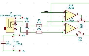
I used trimmer resistors that can be finely adjusted with a screwdriver for the R2 in each feedback potential divider, so that I can adjust every channel's gain to compensate for manufacturing inaccuracies in R1 and make my channels perfectly balanced; more on that later.
The "B" input of the inverting amplifier circuit is my 6V signal ground reference. As the resistors are set up for unit gain, this means that output voltage is 6+(6-input) volts - but if we change our perspective and call that signal ground reference 0V and our power supply lines as +6V and -6V, then the output is just minus the input voltage; the input signal flipped upside down, and nicely buffered.
Why don't we use a unit-gain buffer, and have a near-infinite input impedance, drawing no load from the source? Well, there's a downside to that: along a line cable, radio interference from my many noisy electronic devices will inject current into the line. With a very high load impedance, that current will create a large voltage (because V=IR). Not "sparks and explosions" large, but "making a noticeable amount of noise on my audio signal" large. So having a few tens of kilo-ohms of input impedance is desirable to reduce the voltage changes caused by these tiny noise currents, while still not draining much current from the audio source.
Choosing an op amp.
I went with LM358 dual op amp chips. Each comes in a little 8 pin chip, with two op amps, which is handy as my final design needs no less than twelve op amps and I need to fit them on the board. Why the LM358 when there are many others to choose from? Well, GreatScott! on YouTube said they're his go-to for 12v circuits, and as far as I can tell, all dual op amps in 8-pin packages use the same pinout so I could swap for fancier ones if I wanted to later.
Signal Ground reference
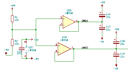
So, I need a "signal ground" reference voltage at 6V, exactly between my 0V and 12V incoming power rails, in order to make the best use of my op-amp's available voltage range. Or should I say, at 0V, exactly between my -6V and +6V power rails. It shouldn't really draw any current, so a simple potential divider between the supply rails would suffice.
However, I've been reading books on radio frequency power amplifier design, and in those high-current high-frequency setups, a big concern is that signals from later stages can leak back into earlier stages through power rails and the like, which creates a feedback loop that oscillates and causes all sorts of trouble. So in the interests of over-designing my little audio mixer as much as possible, I'm going to avoid connecting the two stages of my mixer to the same signal ground, by buffering the reference. Using an extra LM358, my mixer takes a 0V reference created by a potential divider (made from 47k ohms resistors, as I was using them already in the design; and a nice high resistance to not waste much current - about 10 micro amps - while a low enough resistance that it would still require a bit of current draw to disturb the voltage), and feeds that into two unity gain buffers. These copy the input voltage to the output while providing a low impedance output, so I now have two separate-but-identical 0V references.
One, GND1, is connected to the + input of every input amplifier. The second, GND2, is used for the mixing amplifier, which we come to next.
22µF electrolytic capacitors join the +6V and -6V rails where the power comes into the circuit, and also both rails to the two GND rails - which also count as two capacitors in series between the +6V and -6V rails at that point in the circuit (and then that twice in parallel due to the two GND rails). Every LM358 chip also gets a 100nF capacitor from -6V to +6V right next to it. These capacitors mean that any signals that leak onto the four power/ground rails will have a low impedance path to all of the rails, effectively cancelling the signals out.
...yes, this is overkill, but I wanted to see if it would work!
Actually doing the mixing
So, we now have a bunch (four stereo pairs) of nicely buffered input signals, inverted by the input amplifiers, with the ability to drive current. How do we mix them all together?
Well, the first thing we need to do is to put a separate volume control on each. I used 22k ohm logarithmic stereo potentiometers - logarithmic because our ear's loudness response is logarithmic, so a logarithmic knob "sounds" linear to us; 22 k ohm so as to not draw more current than is needed; and stereo so that each one controls left and right for a single channel with a single knob. These are wired from the outputs to ground, with the wipers as the inputs to the next stage, so they act as adjustable potential dividers to control the output voltage.
Because they introduce up to 22k ohms into the signal path, we need to ensure that the input impedance of the next stage is higher than that or it'll draw too much current and upset the potential divider effect.
But, how do we mix those signals together?
Well, remember the second way of looking at the inverting amplifier, based on the current flows? The current flowing in through R1 had to equal the current flowing out through R2 becuase the - input of the op amp won't draw any significant current, and the current through R1 is equal to the voltage from the input A to input B divided by R1. In our circuit we use our 0V reference as input B, so it's just the input voltage divided by R1. And the current flowing out via R2 controls the output voltage.
You may recall Kirchoff's current law, that all the currents flowing into a junction must equal the currents flowing out. So if we connect all the signals, through their own input resistor R1, to the - input of the op amp in an inverting amplifier configuration, then the sum of all those currents flowing in must be the current flowing out via R2. So the output voltage will depend on the sum of all the input voltages! We can generalise the inverting amplifier circuit into a summing inverting amplifier, whose output voltage is B + (R2/R1n)*(B - An) if we have multiple inputs An with input resistors R1n!
So the outputs from my variable resistors can go through 47k ohm R1 input resistors to a common "bus" for left or right respectively:
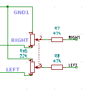
Each each signal then goes into the - input of final LM358 op amp, with a 47k ohm feedback resistor from the output, and the + input connected to the second 0V reference, GND2.
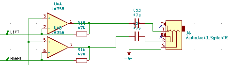
And because it's an inverting amplifier, it inverts the signal back again - as it was inverted once already by the input amplifier. So the output is the same as the input signal as long as the volume knob for that channel is at the top, and correspondingly reduced if not. Perfect!
I also put 10pF capacitors from the left and right common points (the - inputs to the output op amps) to GND2. This is a very small capacitance, so the reactance to ground will be very large compared to the 47k ohm resistances feeding into and out of that point - except at high frequencies. At about 300kHz the reactance gets down to 65k ohms, which starts to compete with the 47k ohms and pull an increasing fraction of the current to GND2 instead of contributing to the voltage across the feedback resistor and, hence, the output. This is useful because any oscillation in the circuit caused by unintended feedback will tend to be at quite high frequencies, in the megahertz; so these two capacitors will kill the feedback loops without cutting the high audio frequency response of the mixer.
Output
The output from the final stereo pair of output op amps is a nice low source impedance signal; we just need to DC-shift it back to being around the "true" 0V line connected to the sleeves of all the 3.5mm sockets, which is our -6V line. But we actually delegate that task to the audio device we send the signal through; we just put the two outputs through a stereo pair of those nice low-impedance-even-at-bass-frequencies 47µF capacitors so it will float to whatever DC bias the device at the other end of the cable wants.
I suspect I could probably have put high-value resistors between all the audio inputs and outputs and the -6V "true ground" to ensure their DC bias is around true ground, which would reduce pops when plugging things in and out, but it's not important.
Implementation
So, that's all the theory. How did I turn that into the actual device?
Firstly, I learnt to use KiCad, the definitive open-source electronic design software. I designed the circuit, then laid out the PCB, routed the tracks. KiCad can generate "gerber" files that I then sent to the cheapest PCB manufacturer I could find (which was JLCPCB at the time of writing), and a week later, had the boards in hand.
Well, it wasn't QUITE like that. The first PCB I made had the stereo log pots wired the wrong way around so minimum volume was when the knob was all the way to the right - which was not only confusing, but it meant that the logarithmic taper on the potentiometer was the wrong way around, so the volume stayed about the same for most of the travel then suddenly dropped to nothing in the final quarter. Also, the pads for the potentiometers were too close together to actually fit them on the board!
So I used that board to assemble the ground reference and output amplifier circuits, and two channels of the input amplifiers, in order to test the design. It worked fine, so when the final boards came I could desolder all my parts from the test board (waste not want not!) and build the full thing for real.
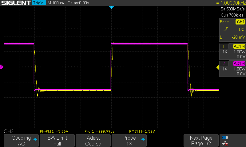
My oscilloscope has a 3.3V 1kHz square wave test signal output, so I used that to test and calibrate the channels; it's bigger than an audio line level, but still well within the voltage range of the LM358s. I used one oscilloscope channel to measure the input waveform and another to measure the output, and adjusted the little trimmers until they exactly overlapped, for each of the eight mono channels.
I did a few other experiments at that point, too. I found that if I fed the square wave into the left side of an input channel while monitoring the right side of the output, I could see little spikes when the square wave switched. I also saw a bit of ringing and some "wiggles" in the switching waveform (which I believe is crossover distortion), which I've zoomed in on here:
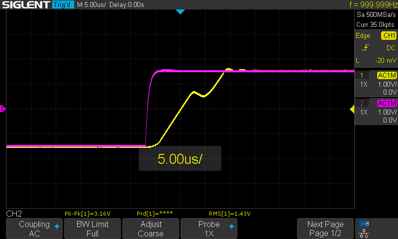
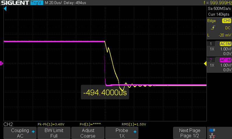
A 3.3V square wave far exceeds the rate of change of input to be found in line audio, so this didn't worry me. I gather I could fix the crossover distortion by swapping my LM358s out for fancier op-amps, for a start!
I also found that, when carrying actual audio signals, it sounded fine until the supply voltage was well below five volts - at around three volts it started distorting the audio. So with my 12V supply I have plenty of headroom!
Capacitor selection
It's easy to drag a capacitor symbol onto your schematic and write "22µF" on it, but then you need to pick a footprint for that part when you get to PCB design. Resistors are easy - unless you get into high powers, all resistors are the same size, but capacitors vary tremendously.
Small capacitances - picofarads and nanofarads - are easy; for the decoupling caps on each chip, I used polyester film 100nF capacitors I have a big bag of for exactly this kind of thing, so I picked a footprint matching them. For the 10pF low-pass filtering capacitors, I found some little ceramic caps and used their footprint. For the 22µF power rail filtering capacitors, I went with electrolytics, as it normal for microfarads and above; I had some little 25V-rated ones handy so used them. But the input/output DC blocking capacitors, which I need to have at least 47µF of capacitance in order to have acceptable bass reproduction, were trickier. I was worried about using electrolytics for this due to not being certain whether the source might put some crazy DC offset on the input, but then I was told by a helpful Redditor that you can get bipolar electrolytics specifically for audio DC blocking applications, so I bought some Nichicon MUSE bipolar electrolytics and used their footprint on the PCB.
Expansion port
I included, on the schematic, a header carrying all the common signals between the parts of the system: -6V, +6V, GND1, GND2, and the left and right "common points" in the mixer. This is just a row of holes in the PCB - I didn't solder a header into them; but I used them to test the design, checking the GND1 and GND2 voltages came out correctly. Without the output stage in place, the outputs of the input amplifiers can be checked here, too - once the output stage is assembled on the board, remember, the output op amps attempt to keep these common points at 0V so an oscilloscope won't measure anything here, as the "real signal" is in the form of a current flowing PAST that point (which I took a moment to get my head around).
However, this header also serves a second purpose. Due to minimum order quantities and the cost of the boards versus the cost of shipping the package, I have 20 of these boards made. Should I want to, I could assemble up to four more input channels (omitting the output circuit and the ground reference circuit) on a second board and connect it to the existing board through these headers. In fact, I could do this with all 20 boards and have an 80 channel mixer, should I ever need one!
But most likely I'll give the spare boards to anybody who wants to make a mixer following my design 🙂
The Experience
Making this thing has been a big deal for me. For a start, I had to learn a lot about operational amplifiers (theory and practice), and the nature of impedance in these kinds of circuits. And then I had to learn KiCad too! But I love learning new things, so this has been great fun - and when the end result worked, didn't sound awful, and will actually be a useful piece of equipment (once I've put it in a box), that's very satisfying!
The Files
If anyone wants to make it themselves, the KiCad files are available here and the gerbers here - enjoy!
Parts you'll need:
- 6 LM358, or similar DIP8 dual op-amp
- 6 8-pin DIP sockets
- 6 100nF film capacitors
- 4 22K logarithmic stereo potentiometers
- 5 22µF electrolytic capacitors
- 8 50Kohm trimmers
- 20 47Kohm resistors
- 2 10pF ceramic capacitors
- 5 3.5mm stereo jacks
- 10 47µF bipolar electrolytic capacitors
![]() Alaric, Electronics | alaric |
Alaric, Electronics | alaric | ![]() Tue 9th Feb 2021 4:40 pm
Tue 9th Feb 2021 4:40 pm
