The “Mr Redox” Home Energy Reactor (by alaric)
Construction
I made the firebox from Vitcas castable refactory, in wooden forms; and the secondary burn tube from the same mixed with perlite, using two nested carboard tubes as forms, which I just burnt away rather than attempting to remove the tube from the mould.
The primary heat exchanger was welded together from 3mm thick mild steel sheet, as was the door and the other metalwork, and painted with barbeque paint. I was concerned that the interior of the heat exchanger would corrode with time, so I nickel-plated it; I turned it upside down, filled it with nickel plating salt solution, dangled sacrificial nickel anodes into it with wires, hooked the heat exchanger up as the cathode, and ran current through it for several days until a thick layer of nickel had deposited on the interior.
The secondary heat exchanger tubes are made from the same stuff as the chimney visible in the picture - 100mm galvanised steel flue pipe. You can get various junction parts ready-made, and just attach them using pop rivets, then use high temperature silicone to make them airtight.
The three horizontal tubes in the secondary heat exchanger terminate at the far end in T junctions with removable end caps, so I can open it up to inspect and clean it.
I built brickwork up around all this as I went, then filled the secondary heat exchanger with sand, laid some nice paving tiles on top, and that was that. I'd like to get some smaller tiles to go around the top of the firebox where the primary heat exchanger sits, to neaten up the gap between the heat exchanger base plate and the edges, but I've not gotten around to it yet.
The Vacuum Ejector
When I started test-firing, I found it hard to light the thing. The problem was that I'd made the secondary heat exchanged oversized compared to the size of the burn chambers - so the flue gasses were too cool by the time they got to the bottom of the chimney, and didn't rise. When I removed the end cap at the bottom of the chimney to take a look inside, smoke poured out and, creepily, just pooled around my ankles.
I found that I could get it burning well if I used a compressed air gun to blow the smoke up the chimney, then replaced the end cap as soon as it was going; once it was running at a proper temperature, the flue gasses were warm enough to rise on their own and pull air through the system, but when everything was cold to begin with and the fire just getting started, it wasn't enough, and the fire ended up being put out by its own carbon dioxide build-up.
(As an aside, I fitted a carbon monoxide alarm in the workshop to make sure this didn't kill me, too).
So as a longer-term fix to this, I built a vacuum ejector. On the outside, it looks like this:

The copper pipe coming down parallel to the chimney is hooked up to my workshop compressed air line. The regulator drops this air - which is at quite a high pressure - down to something around 200kPa above atmospheric pressure, and when the red valve is opened, this air is fed up the flexible tube and into the ejector assembly itself. Inside the chimney is a length of standard 15mm copper plumbing pipe, capped at the other end, with a three millimetre hole drilled in the top, facing up the chimney. When compressed air rushes out of that hole, via the Venturi effect, it sucks the flue gasses up with it. This makes the fire in the firebox roar vigorously, and makes starting the heater a breeze!
Starting it
To start it, I clean out the ashes from the firebox, then stack it up with wood, and sometimes a dollop of sawdust soaked with waste vegetable oil from our chip fryer. I put some screwed up paper in front of that, and a few scraps of cheese wax if I have them.
I then turn on the vacuum ejector, light the paper, and close the door. Within a few minutes, when the primary heat exchanger temperature is over three hundred celcius, I shut off the ejector and it runs itself. All the wood I can fit in the firebox will have burnt out within half an hour, so I often keep throwing new chunks into the embers and stirring them a bit with a poker to keep it going. But after an hour or so of that, the room is usually warm enough, and I let it burn down for the rest of the day, maybe running it a bit more in the early afternoon if it's a really cold day.
Monitoring
A lot of the interesting stuff happening inside is rather hidden, so I embedded a number of stainless steel K-type thermocouples, which can cope with extreme temperatures. The first is at the top of the primary heat exchanger, the second is at the junction from the primary to secondary heat exchangers, the third is buried in the sand in the middle of the secondary heat exchanger, and the fourth is in the chimney just where it exits through the roof.
To begin with, I monitored them with a multimeter capable of reading thermocouples, which meant having to move crocodile clips between the different connections to read them, but last weekend I fitted a bunch of MAX6675 modules to an Arduino and hooked up the three thermocouples at the front end of the heater, on a breadboard:

The firmware on the device just uses the USB serial port to print the temperatures (in Celcius) of the first three thermocouples, once per second, but that was enough for me to log the temperature during a startup (click to make it big):
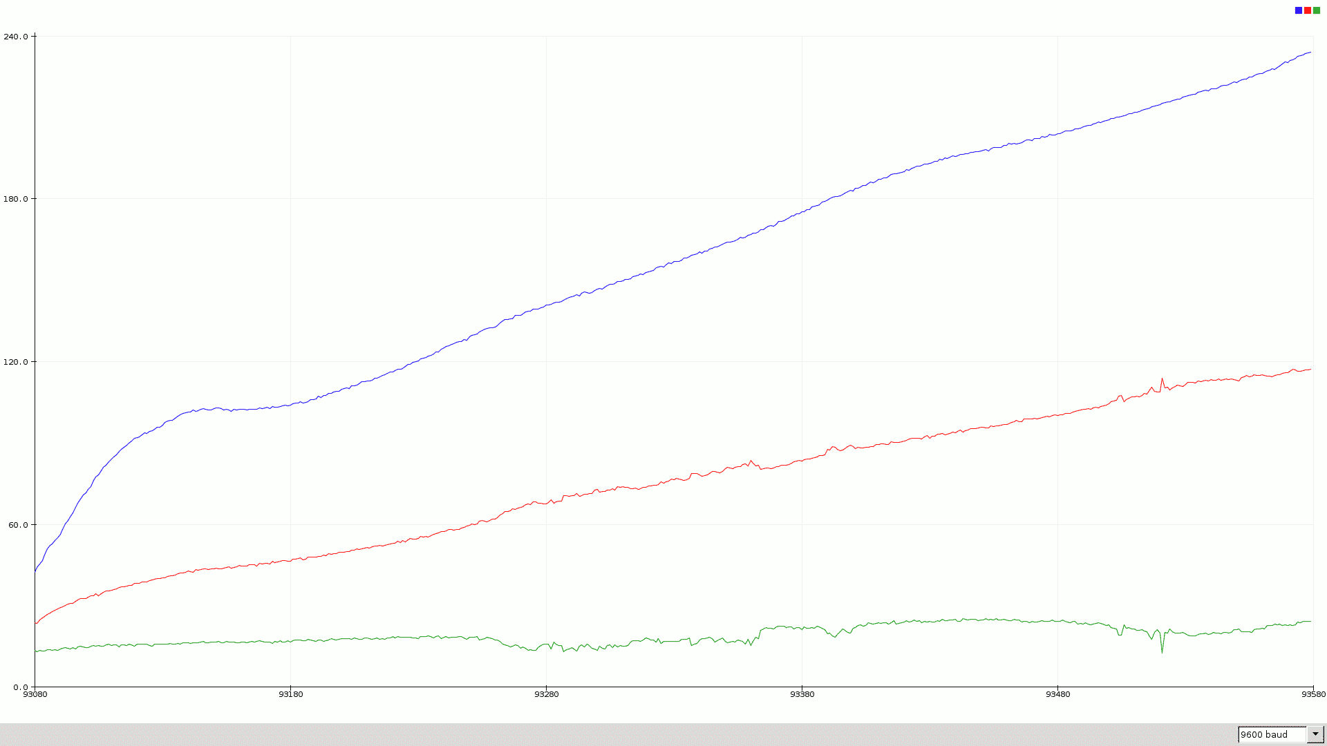
The horizontal scale is about five hundred seconds, the blue curve is the primary heat exchanger temperature, the red curve is the heat of the gasses going from the primary to secondary heat exchangers, and the green curve is the temperature in the sand inside the secondary heat exchanger. The primary heat exchanger is quite efficient, so the temperature on the outside of it (measure with an infrared thermometer) is generally within a few degrees of the gas temperature inside as shown on the blue curve.
You can see a sharp initial rise as the paper burns, which then flattens after about a minute; but then the wood starts burning in earnest and the temperature rises steadily.
Oddly, the secondary exchanger temperature (green curve) drops a bit after a while; I expected it to lag well behind the other curves as the heat has to conduct through a bunch of sand, and it does rise in the end, but after about one hundred and eight seconds, it seems inversely related to the temperature of the gasses flowing into the secondary heat exchanger (red curve) on a short time scale. I have no idea why this is - perhaps it's just some kind of noise affecting the thermocouple signals rather than an actual physical thing happening? It doesn't make much sense to me, but I won't worry about it until my monitoring setup isn't on a breadboard!
My long-term plan is to build a CAN bus and 12v DC power distribution around the workshop, to connect a bunch of control and monitoring systems together - the first part of which will be adding an MCP2515 to this breadboarded setup, and another for the single thermocouple at the far end of the flue, so I can experiment with CAN bus and get all four thermocouple outputs together. Once I've gotten a working prototype, I can make it all again on proper PCBs in proper enclosures and run proper cabling through my cable trays to hook it up - and the first arm of the CAN network will be in place! I'll breadboard a CAN interface to my desktop PC to read off monitoring information to begin with, but I want to have a raspberry Pi dedicated to feeding that into my proper monitoring system in the long run, and I might make a little desktop "control box" with readouts for sensors and pushbuttons for CAN controlled things (like the lights) - we'll see!
Conclusion
I've had a lot of fun, and learnt a lot, making this thing. For instance, I made the secondary heat exchanger too effective; at some point I may improve it by removing the sand and tubing and just letting it be a big box full of hot flue gasses, with some kind of airtight top supporting the cushion, and bring the chimney tube down so that only the cooler gasses which have sunk to the bottom can escape. That would reduce the resistance to flow and the cooling effect so the heater would be much easier to light, and the outside of the box would get hotter and radiate more heat - at the cost of it not keeping the heat so well overnight, but I could live without that in exchange for faster heating of the room!
I'm looking forward to finishing off the cosmetic trim around the front end, and building a final thermocouple interface into the CAN bus too - watch this space 🙂
But most importantly, it warms this room, very efficiently turning our scrap decking wood into heat!
Pages: 1 2
![]() Alaric, Building Maintenance, Sci/Tech | alaric |
Alaric, Building Maintenance, Sci/Tech | alaric | ![]() Sun 28th Mar 2021 4:31 pm
Sun 28th Mar 2021 4:31 pm

By Priya Samuel, Sun 28th Mar 2021 @ 7:54 pm
Fascinating!! Until now I thought the rocket mass heater was a fancy name for a fireplace. And also, I’m so glad that Helium isn’t combustible 😉
By Joel, Mon 26th Apr 2021 @ 9:17 am
Hej! I'd like to build a rocket mass heater like yours with a proper bottom part like a normal wood-burning stove.
Can you share your drawings, tips and experiences of building a RMH? J